A.Select Displays and Camera
1.Launch VIOSO Integrate from the desktop.
2.On opening, you may see a prompt stating ‘Overlap detected’. Click Yes.
3.Select Calibrate to begin.
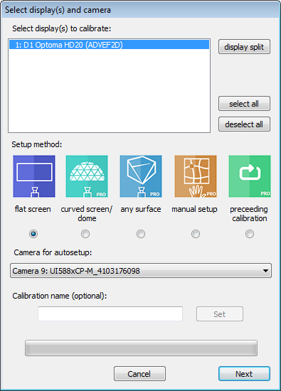
4.Select single client calibration and then you should see a window like this:
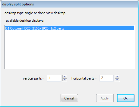
5.Select ‘display split’.
6.Set the number of vertical parts/horizontal parts to match the Eyefinity or Mosaic group and apply:
7.Select all displays for the calibration and the screen type for Setup method:
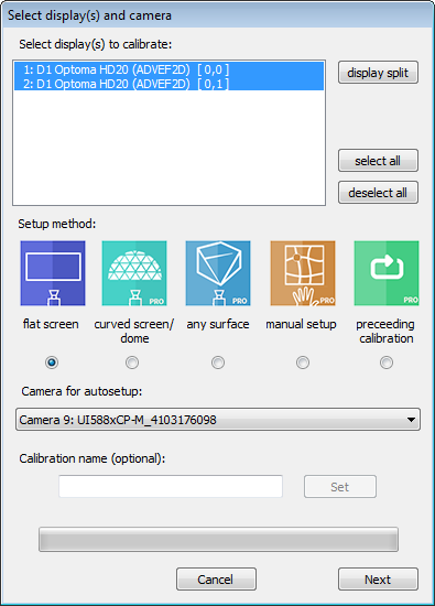
8.Set the projector arrangement to match the arrangement on screen.
9.Set any Extended Options as desired, or use defaults.
10.Adjust the camera rotation as necessary under Options > Image Processing:
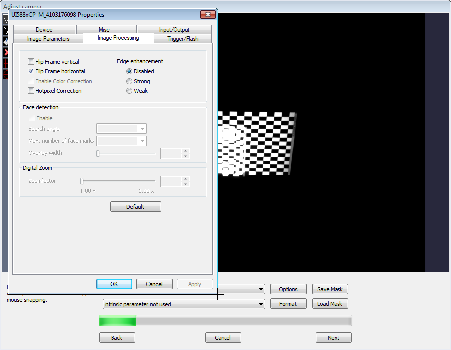
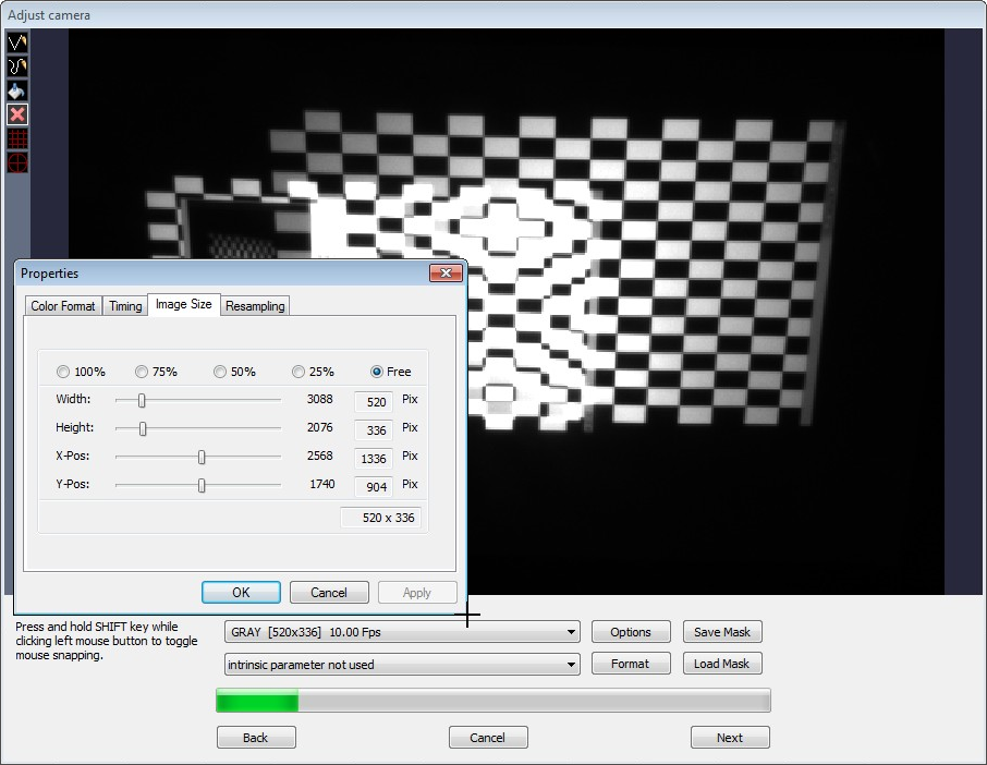
11.Adjust the camera zoom under the Format menu to zoom into the screen shape, which reduces processing time:
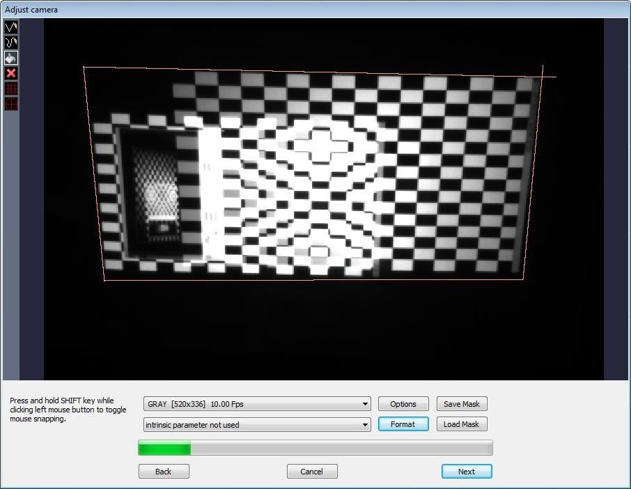
12.Draw a mask around the screen area. Single click to set the first point, double click to end a line making sure to overlap your lines:
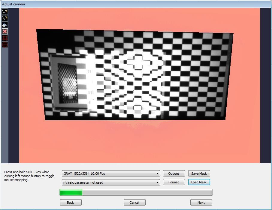
13.Fill the unwanted region of the image with the paint bucket tool and optionally save the mask:
14.Select Next
B.Geometric Correction
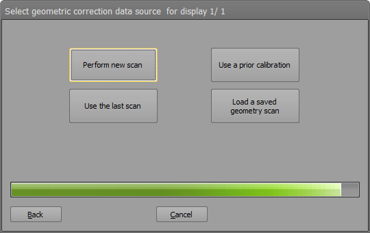
1.If asked which set of geometric correction data source to use, select Method: ‘Perform new scan’.
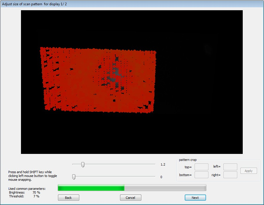
2.If the initial result does not yield bright green circles, press back to adjust the noise filter, otherwise, proceed to step 5, ‘Adjust geometry scan inspection options’.
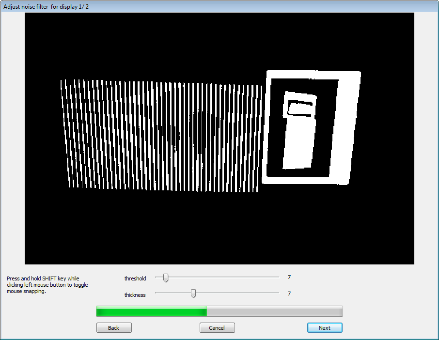
3.Adjust the threshold and thickness until you have thin, distinct lines across your entire projected surface and click Next.
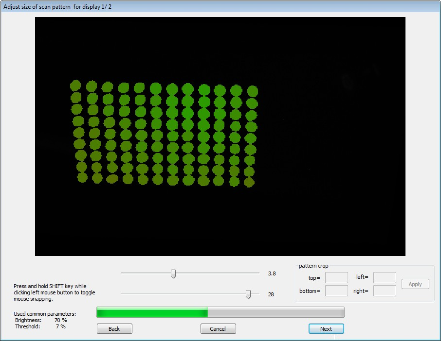
4.Adjust the sliders to change the circle size and spacing until you have distinct green circles, then select Next.
5.Adjust geometry scan inspection options.
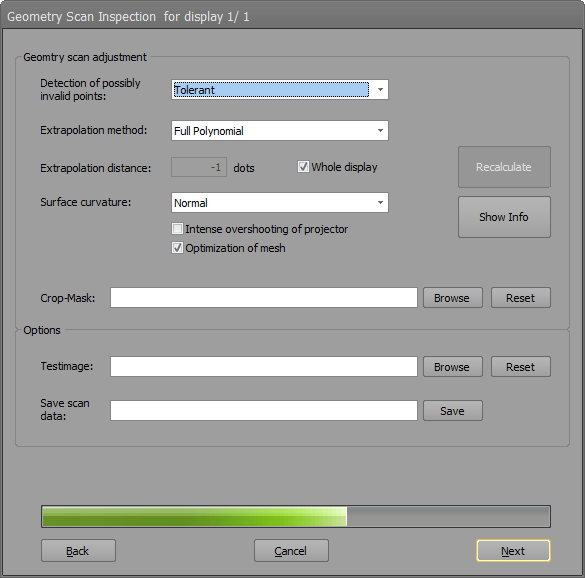
a.You can control extrapolation and geometry fitting.
b.If you change something, press recalibrate and check on screen.
c.Press ‘Show Info’ to get extended information about measurements.
d.You can adjust strictness on outliers.
e.Select ‘Full Polynomial’ (standard extrapolation method / preferred) if all points are on a simple geometry, like sphere or cylinder.
f.Select ‘Partial Polynomial’ (alternative extrapolation method / use geometry does not match in overlaps – adds unwanted waviness on corners) for arbitrary shapes (but still the shape needs to be continuous [no corners]).
g.Number of points that must be extrapolated (-1 = whole display). Check if needed area is covered by projection.
h.Change ‘Surface curvature’ for extreme screens.
i.Check ‘Intense overshooting of projector’ if a big part of the projection is not displayed on the screen.
j.Uncheck ‘Optimization of mesh’ if the shape does not match the real screen.
k.You can use cropping masks to cut parts of the projectors and change blending zones.
l.Load your own test image.
m.Save calibration for further use or for debugging send to VIOSO.
6.Once the calibration is complete for the first display, click Next and repeat stage 3. Geometric Correction for remaining displays.
7.Adjust the points – adding more as necessary – to define your screen bounds.
C.Export MPCDI Data
1.In the Calibrator software, select File > Export Mapping.
2.Select the target display (not the individual displays) and your desired format from the dropdown.
3.Tick ‘Individual split export’.
4.Tick ‘Virtual content rects’ in case you want to let VIOSO do the slicing; you’ll find a ~_def.txt containing optimal content size and scanouts.
5.Set your file name. To change the folder, use the ‘Browse’ button.
6.Click ‘Export’.