Projection Mode
Projection Mapping is the art of using projectors to paint media onto complex surfaces. Most projector lenses are designed for tangential mapping, meaning that when a projector’s light source produces an array of pixels and passes that through, the lens is designed to produce a uniformly lit, uniformly focused rectangle of light on a flat plane surface. Success depends on the projector being pointed square at the surface, and the surface reflecting the light uniformly back to the viewer’s eyes. The key challenges of projection mapping are therefore dealing with geometry and luminance (the intensity of light reflected/emitted from a surface), compensation or compromise, when projecting onto non-planar objects with varied surface properties, generally from multiple blended projectors shooting from disparate angles, and often in environments where viewer position varies greatly.
All these factors should be considered in planning a projection mapping. Simple, right? Tools like DeltaServer hide much of the challenge by predicting geometry and light behaviour in a 3D space. The resulting image relies on a sensitive static relationship between projectors and surface, so care should be taken in installing the projectors in relation to the target, in a stable manner that will change as little as possible in the future. Any changes will result in the need for alignment adjustment.
The 3D Object/Surface
 |
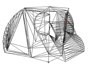
Geometry and light predictions are accomplished by placing a virtual camera representing each real world projector in the software’s 3D space, whose X, Y, Z, heading, pitch, roll and lens characteristics closely match that of the real world projector lens. So long as the geometry of the 3D model accurately matches that of the real world object, you will accomplish an accurate reflection of that camera’s view of the textured software model back onto the real world object. Texturing the model means defining how 2D content will be applied to a 3D mesh of faces. DeltaServer supports both explicit UV maps (a list embedded in the .obj model file, defining relationships between 2D canvas x,y percent positions to 3D points on the model), as well as eyepoint-based virtual projection. |
The 3D Model
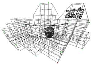 |
A 3D model is a system of co-ordinates (‘nodes’ or ‘vertices’) joined in a mesh. The co-ordinates take as their reference a zero-point (or origin) within (or outside) the model of the reference object. The model can be rotated and viewed from any angle, but when used for projection mapping, the designer will take a chosen viewpoint (or eyepoint) that ‘projects’ an orientation from which the object will be viewed. |
The 2D Media
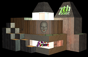 |
Because the designer’s reference point is the origin of the model, the media effectively represents what the origin of the model would see in a mirror. For better and sharper results, the media can be displayed over several projectors, and it may be better to split a complex mesh model into more manageable pieces for those projectors, but projection mode still assumes that the designer and viewer are both looking at the media-painted object from the same view of the model. |
Textured Mode
The 3D Object/Surface
 |
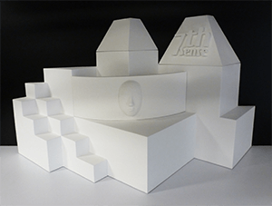
Just as the 3D model can be rotated and viewed from any angle, so the viewer can either move around the model, or the object can be rotated, and the media will ‘stick to’ and move precisely with the object. Here is a demonstration model of a totem head with easy-to-identify surfaces. |
The 3D Model
 |
The 3D model is constructed in the same way, but its entire external surface is notionally ‘peeled off’ or unfolded onto a flat surface. This surface is ‘painted’ by the designer to create specially rendered 2D media. Whilst the object and model are described in X × Y × Z axes, the surface is described in the 2D U × V axes, hence UV-rendered or mapped media. |
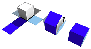 |
In this illustration a simple cube demonstrates the theory of what can be actually a more complex mapping, as in the ‘totem head’ example used here. |
The 2D UV-Mapped Media
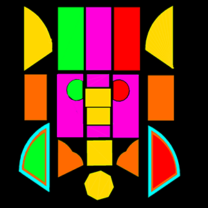 |
For the designer, all viewpoints now are perpendicular to the model/object surface, rather than, say an oblique view of the side of a cube. In textured mode, the characteristics of the mesh model surface are ‘baked’ into the flat media, which is then folded back onto the model in the projection. Compare this UV-mapped media frame with the one used above for projection mode. The top row of faces are projected on the other side of the object, either by rotating the object into projector view, or by providing all-round channel coverage. The reason this media does not look simply unfolded as in the cube above, is that this would create a lot of empty space in every frame. Instead, the elements are packed into the 2D space, with mapped coordinates that are used to place them on the target object or canvas. |
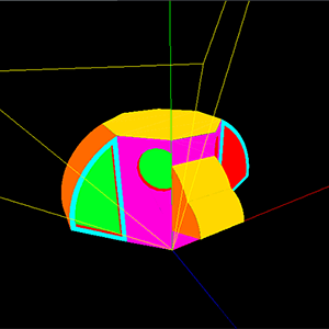 |
This is how the UV media looks in the Playback Window when ‘folded’ or positioned back onto the model, as seen from a single channel. The yellow lines show the model origin (X,Y,Z = 0,0,0); red, green and blue are the X, Y, Z axes. |